Waterproof model of sealing gasket for segment joint
The waterproof form of the tunnel segment joint gasket selected in this study is the type of separate arrangement of inside and outside, that is, two rubber gaskets are arranged separately on the upper and lower sides of the segment joint section, and the lower side of the rubber gasket is preset in the lower part of the water expansion sealing strip. Seam material protection, waterproof failure on the upper side of the gasket is waterproofed by the lower side, the composite elastic rubber gasket is designed separately from the water expansion sealing strip, and the bolt holes are reserved in the two composite elastic rubber gaskets, so that the waterproof material on the surface of the segment can give full play to the waterproof effect.
The waterproof working principle of the annular gasket at the joint of the segment structure mainly includes the following two aspects:
-
1.
Extrusion sealing: Under the action of axial load pressure, the annular gasket produces the axial extrusion pressure of the segment, which improves the sealing effect of the gasket. The sealing performance and lifespan of the sealing gasket are two important indicators of the amount of compression.
-
2.
Self-sealing effect: The water pressure acts on the inner wall of the segment joint, and the gasket produces the tensile deformation of the expansion in the gasket, thus increasing the friction and shear force of the axial contact interface and improving the sealing effect.
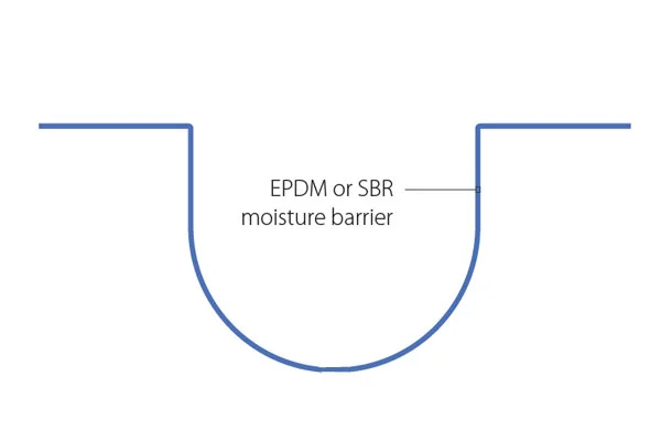
When the joint of the tunnel segment structure is subjected to water pressure, the effect of water pressure on the gasket can be decomposed into radial and vertical directions. The radial water pressure has a shear effect on the contact surface of the gasket to overcome the friction resistance among the gaskets. The vertical water pressure reduces the contact pressure stress on the surface of the gasket, creating conditions for the radial water pressure to break through the seal. If the joint structure is staggered, in addition to the above load, it will also generate friction among the gaskets or among the contact surface of the test block. It is assumed that the unit width of the longitudinal section of one side of the two continuous tunnel segments is selected for force analysis, and the waterproof model of the annular sealing gasket of the longitudinal section of the segment is established20, as shown in Fig. 1. Among them, Pw represents the magnitude of water pressure, Aw represents the axial water pressure area along the joint, and T represents the elastic restoring force of the gasket. Due to the different openings on the upper and lower sides of the joint of the tunnel segment structure caused by external factors, the elastic restoring force also varies. F represents the friction among the gaskets. In addition to the forces mentioned above, other external forces, such as the connection load of the tunnel segment structure and the selfweight of the structure, are denoted as F.

Waterproofing model of segment longitudinal section joint gasket.
Mechanical calculation
It is assumed that the sealing waterstop and specimens conform to the basic assumptions of elastic mechanics. As shown in Fig. 1, at the time of t0, when the joint specimens are not subjected to water pressure, but the sealing waterstop is, the equilibrium state is maintained, and the resultant force in the X direction is zero.
$$T_{1} ({\text{t}}_{0} ) + T_{2} ({\text{t}}_{0} ) – F({\text{t}}_{0} ) = 0$$
(1)
At time t1, when the assembled joint is subjected to water pressure due to external factors, if the other external force F is unchanged at this time, there is
$$T_{1} (t_{1} ) + T_{2} (t_{1} ) – F(t_{1} ) – P_{{\text{w}}} A_{w} = 0$$
(2)
From Eqs. (1) and (2), we know
$$\Delta T_{1} + \Delta T_{2} = P_{{\text{w}}} A_{{\text{w}}}$$
(3)
The compression line of the waterstop belt, with a stiffness of kT, \(h\) is the height of the elastic gasket and has the following calculation formula,
$$k_{T} = E_{T} A_{T} /h$$
(4)
At this time, the additional opening of the joint of the shield segment assembly structure caused by the water pressure is Δx1. Because the upper and lower sides of the joint of the shield segment assembly structure will have different openings due to external factors, the total openings of the upper and lower sides of the structural joint are Δx1 and Δx2, respectively.
$$\Delta T_{1} = k_{T} \Delta {\text{x}}_{{1}}$$
(5)
$$\Delta T_{2} = k_{T} \Delta {\text{x}}_{{2}}$$
(6)
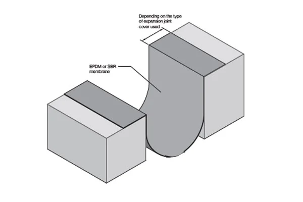
If ∆ × 1 is the opening of the upper joint, ∆ × 2 is the amount of opening on the lower side of the joint of the corresponding structure that is different. That is, the corresponding structure deviates to the inside, as shown in Fig. 2, in which ∆ × 1 and ∆ × 2. For the opening of the structural joint at θ angle, ∆ × 1’ and ∆ × 2´ is the opening amount of the structural joint when the structure is offset to θ´, and b is the height of the structural joint, which is obtained by the geometric relationship
$$2b\sin \theta + \Delta {\text{x}}_{1} = \Delta {\text{x}}_{2}$$
(7)
Schematic diagram of upper and lower openings of segment structure joints.
Equations (5), (6), (7), and substitution Formula (3) are available.
$$\Delta {\text{x}}_{{1}} = \frac{{P_{w} A_{w} – 2k_{T} {\text{bsin}}\theta }}{{2k_{T} }}$$
(8)
$$\Delta {\text{x}}_{{2}} = \frac{{P_{w} A_{w} + {2}k_{T} {\text{bsin}}\theta }}{{{2}k_{T} }}$$
(9)
Equations (8), (9) into (5) and (6) are available.
$$\Delta {\text{T}}_{{1}} = k_{T} \frac{{P_{w} A_{w} – {2}k_{T} {\text{bsin}}\theta }}{{{2}k_{T} }}$$
(10)
$$\Delta {\text{T}}_{{2}} = k_{T} \frac{{P_{w} A_{w} + {2}k_{T} {\text{bsin}}\theta }}{{{2}k_{T} }}$$
(11)
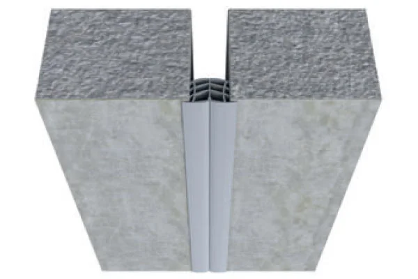
The unit body of the sealing waterstop is selected for analysis, as shown in Fig. 3.
Stress diagram of sealing waterstop under water pressure.
When the joint is not affected by water pressure, from the initial conditions and boundary conditions,
$$\left\{ {\begin{array}{*{20}l} {\sigma _{{x{1}}} = \sigma _{{{\text{01}}}} } \hfill \\ {\sigma _{{x{2}}} = \sigma _{{{\text{0}}{2}}} } \hfill \\ {\sigma _{y} = 0} \hfill \\ {\sigma _{z} = \sigma _{0} } \hfill \\ {\varepsilon _{{x1}} = \varepsilon _{{{\text{01}}}} = \Delta h_{1} /h} \hfill \\ {\varepsilon _{{x{2}}} = \varepsilon _{{{\text{0}}{2}}} = \Delta h_{{2}} /h} \hfill \\ \end{array} } \right.$$
(12)
Substituting Eq. (12) into the physical equation of elastic mechanics of the element body21, we can obtain
$$E_{T} \varepsilon_{01} = \sigma_{01} – \upsilon \sigma_{0} = \sigma_{01} \left( {1 – \upsilon^{2} } \right)$$
(13)
$$E_{T} \varepsilon_{02} = \sigma_{02} – \upsilon \sigma_{0} = \sigma_{02} \left( {1 – \upsilon^{2} } \right)$$
(14)
When the shield segment assembly joint is subjected to water pressure with a pressure of pw, considering the friction between the upper and lower surfaces, there are
$$\left\{ {\begin{array}{*{20}l} {\sigma _{{x{1}}} = \sigma _{{p{\text{1}}}} } \hfill \\ {\sigma _{{x{2}}} = \sigma _{{p{2}}} } \hfill \\ {\sigma _{y} = p_{{\text{w}}} } \hfill \\ {\varepsilon _{{x{1}}} = \varepsilon _{{{\text{01}}}} = \left( {\varepsilon _{{01}} h_{{1}} – \Delta x_{1} } \right)/h_{1} } \hfill \\ {\varepsilon _{{x{2}}} = \varepsilon _{{{\text{0}}{2}}} = \left( {\varepsilon _{{0{2}}} h_{{2}} – \Delta x_{{2}} } \right)/h_{{2}} } \hfill \\ {\sigma _{z} = \sigma _{f} } \hfill \\ \end{array} } \right.$$
(15)
Substituting Eq. (15) into the physical equation of elastic mechanics, we can obtain that
$$E_{T} \varepsilon_{01} – E_{T} \frac{{\Delta x_{1} }}{{h_{{}} }} = \sigma_{p1} \left( {1 – \upsilon^{2} } \right) – p_{w} \left( {1 + \upsilon } \right)\upsilon$$
(16)
$$E_{T} \varepsilon_{02} – E_{T} \frac{{\Delta x_{2} }}{h} = \sigma_{p2} \left( {1 – \upsilon^{2} } \right) – p_{w} \left( {1 + \upsilon } \right)\upsilon$$
(17)
Simultaneous Eqs. (8), (9), (13), (14), (16), and (17), we obtain
$$\sigma_{p1} = \sigma_{01} + p_{w} \left[ {\frac{\upsilon }{{\left( {1 – \upsilon } \right)}} – \frac{{E_{T} A_{w} }}{{2k_{T} h\left( {1 – \upsilon^{2} } \right)}}} \right] + \frac{{E_{T} b\sin \theta }}{{h\left( {1 – \upsilon^{2} } \right)}}$$
(18)
$$\sigma_{p2} = \sigma_{02} + p_{w} \left[ {\frac{\upsilon }{{\left( {1 – \upsilon } \right)}} – \frac{{E_{T} A_{w} }}{{2k_{T} h\left( {1 – \upsilon^{2} } \right)}}} \right] – \frac{{E_{T} b\sin \theta }}{{h\left( {1 – \upsilon^{2} } \right)}}$$
(19)
Substituting Eqs. (4) into (18) and (19), the contact compressive stress on the surface of the sealing waterstop is obtained as follows
$$\sigma_{p1} = \sigma_{01} + p_{w} \left[ {\frac{\upsilon }{{\left( {1 – \upsilon } \right)}} – \frac{{A_{w} }}{{2\left( {1 – \upsilon^{2} } \right)A_{T} }}} \right] + \frac{{k_{T} b\sin \theta }}{{\left( {1 – \upsilon^{2} } \right)A_{T} }}$$
(20)
$$\sigma_{p2} = \sigma_{02} + p_{w} \left[ {\frac{\upsilon }{{\left( {1 – \upsilon } \right)}} – \frac{{A_{w} }}{{2\left( {1 – \upsilon^{2} } \right)A_{T} }}} \right] – \frac{{k_{T} b\sin \theta }}{{\left( {1 – \upsilon^{2} } \right)A_{T} }}$$
(21)
Perhaps
$$\sigma _{{p1}} = \sigma _{{01}} + p_{w} \frac{\upsilon }{{\left( {1 – \upsilon } \right)}} + \frac{1}{{2\left( {1 – \upsilon ^{2} } \right)A_{T} }}\left( {2k_{T} b\sin \theta – p_{w} A_{w} } \right)$$
(22)
$$\sigma_{p2} = \sigma_{02} + p_{w} \frac{\upsilon }{{\left( {1 – \upsilon } \right)}} – \frac{1}{{2\left( {1 – \upsilon^{2} } \right)A_{T} }}\left( {2k_{T} b\sin \theta + p_{w} A_{w} } \right)$$
(23)
In the formula,
\(\sigma_{01}\)—the compressive stress on the surface of the upper side gasket before the action of water pressure.
\(\sigma_{02}\)—the compressive stress on the surface of the lower segment gasket before the action of water pressure.
\(p_{w}\)—the size of the water pressure.
\(A_{w}\)—the water pressure area along the axial direction of the joint.
\(A_{T}\)—the contact area of the sealing waterstop \(k_{T}\).
\(\upsilon\)—compression line stiffness and Poisson’s ratio of the sealing waterstop.
\(b\)—structural joint height.
\(\theta\)—structural offset angle.
It can be seen from the contact compressive stress formula that the waterproof performance of the gasket depends not only on its own contact area, linear compression stiffness, and Poisson’s ratio but also on the size of the joint opening caused by the height of the segment joint specimen and the inclination angle. As the Poisson’s ratio of the gasket increases, the waterproof performance of the gasket improves. When the height of the structure is constant, increasing the inclination angle of the structural joint will increase the extrusion sealing resistance of the upper gasket and improve the waterproof performance. An increase in the water pressure of the upper-side gasket will result in a decrease in the extrusion sealing resistance of the lower-side gasket. Therefore, the inclination angle of the structural joint has a significant impact on the waterproof performance of the gasket. However, a larger inclination angle of the structural joint will result in a larger assembly space, which can easily damage the edge angles and end faces of the segment joint. Therefore, the inclination angle should be adjusted with an appropriate offset rate.
According to the sealing principle, the contact compressive stress on the surface of the gasket is an important index to measure its waterproof performance20. For a given gasket, the greater the contact compressive stress on the surface of the gasket, the higher the water pressure on the gasket’s surface.