Maintenance and preservation techniques for wall surfaces
Common issues in the maintenance and preservation of ancient brick wall surfaces include efflorescence, biological damage, and powdering, which are salt-hydration phenomena [65, 66] (Fig. 10b–e). These issues are all caused by severe seepage in certain areas of the brick wall [67], and surface maintenance and preservation, as well as moisture-proof and anti-seepage treatments after restoration, are required for different degrees of damage [68]. These problems have received widespread attention.
Firstly, the root cause of the damage, which is water seepage, should be addressed to prevent further deterioration. Maintenance should be performed on damaged waterproof boards, roofs, and drainage structures to prevent further water erosion of the ancient bricks. Additionally, non-contact water vapor content testers [69, 70] can be used to monitor the moisture inside the wall in real-time. After cutting off the root cause of the disease, the material’s intrinsic properties should be determined to assess its sensitivity to efflorescence. The sensitivity of similar ancient bricks may vary, and relevant studies have confirmed that testing using the ASTM C67/C67M-23 standard test method [71] for sampling and testing of bricks and structural clay bricks is reliable. The sensitivity to efflorescence is evaluated by observing the weathering phenomenon, with the ancient brick sample immersed in distilled water for a week. If no weathering is observed, it indicates that the efflorescence sensitivity is low under the specified lighting conditions, as the weathering cannot be seen from a distance of 3 meters or more.
To exclude the interference of internal factors, internal pore moisture should be eliminated after the sensitivity of the ancient bricks is clearly identified. For the treatment of efflorescence-related diseases, traditional techniques tend to favor direct water washing, which may result in secondary water infiltration into the wall surface and make it difficult to accurately control the washing degree. The latest research has shown that electrochemical desalination techniques have achieved significant effects, although they are more costly. This innovative approach avoids the direct washing of the wall with clean water, which can activate the salt content deep within the wall. At the same time, it reduces the negative effects of the treatment method on historical building walls to a much lower extent than washing with clean water. LM Ottosen et al. [72] have shown that electrostatic removal methods can effectively eliminate the corrosive effects of nitrates on brick materials. By applying an external direct current electric field to the brick surface (as shown in Fig. 6, the removal effect is achieved even when the initial nitrate concentration inside the brick is below 50 mg/kg. Applying an electric field to bricks with high initial salt content (2200 mg/kg) can reduce the salt concentration to 270 mg/kg, indicating a significant desalination effect. However, the research on desalination devices needs improvement because it does not prevent the salt produced by the “desalination electrodes” from entering the brick material. Studies have shown that the salt produced at the positive electrode is more corrosive to the brick compared to that at the negative electrode, and the desalination process should avoid secondary damage. Rorig-Dalgaard [73] also encountered similar issues in the study of using electrochemical methods to remove salt from architectural heritage materials. Therefore, they proposed a desalination method using multiple layers of electrodes (Fig. 7), which effectively inhibits the secondary penetration of salt from the cathode plate into the brick material. Based on the different types of salt efflorescence, the anode or cathode plates can be improved accordingly to achieve inhibition effects.

Electrostatic Desalination Device [72]
Multi-layer Electrode Device for Suppressing Secondary Salt Ingress [73]
After eliminating the moisture within the wall’s internal voids, a protective layer is applied to the brick surface, such as a waterproof layer and a hydrophobic layer. Before applying the waterproof layer, the brick wall surface should be cleaned with deionized water to remove surface dust. Then, after the treatment area has dried, a consolidation layer is applied for protection. After the treatment, the coated material is allowed to fully permeate into the brick wall under natural conditions for 3–5 days, at which point the waterproof layer’s sealing and protective functions are maximized. If the previous drainage measures are not carried out thoroughly, it can result in internal moisture retention with external sealing, the moisture within the ancient brick material will be expelled along the path of least resistance. If the transmission path is inward, it can lead to the development of hydration diseases within the brick’s internal facing. If the transmission path is towards the external waterproof layer, cracks in the waterproof layer can increase efflorescence and lead to secondary damage [74, 75]. When selecting a waterproof layer, from a functional perspective, it is advisable to avoid materials with extremely low porosity and strong shielding properties. From the perspective of historical building restoration principles, it is advisable to avoid color-heavy and irreversible coating products. For example, Hao et al. [7] developed a 3–5 μm transparent waterproof coating technology based on polyfluoroalkyl acrylate materials (Fig. 8), which has been demonstrated to provide an efficient thin layer of protection for the brick surface structure, with excellent waterproofing and durable weather resistance. The treated bricks achieve a contact angle of 133° with surface moisture, and the water absorption rate is reduced from 16.1 to 2.8 wt%; C. Kapridaki et al. [8] developed a brick and stone waterproof coating with self-cleaning properties by adding silica oligomers to a mixture of titanium and silicate alcohols. The waterproof layer has been confirmed to have an excellent sealing effect on the brick wall surface, but complete sealing of the brick wall’s internal moisture and water vapor can lead to unpredictable internal damage, resulting in secondary damage after sealing. Given the limitations of waterproof layers, practical applications tend to favor hydrophobic layers such as silane protective layers [6, 76] and polydimethylsiloxane (PDMS) hydrophobic layers [77]. Similar to waterproof layers, hydrophobic layers are not permeable to water but allow the passage of water vapor, which to some extent prevents secondary damage caused by residual moisture inside the wall. Soulios et al. [6] have confirmed that hydrophobic layers significantly reduce the water absorption of brick wall materials in practical applications and effectively mitigate the issue of wall interior moisture retention. Furthermore, the hydrophobic effect of the treated bricks was proven to be almost unaffected by long-term UV aging and water immersion through artificial aging tests (Fig. 9). Due to their good compatibility and practicality, hydrophobic layers have been widely applied in actual engineering projects, achieving remarkable results in the restoration of modern historical buildings such as the Qingdao Changzhou Road Prison [78] and the Shanghai Jiangwan Stadium [31]. However, the use of protective layers has been a subject of controversy, with concerns raised about the potential to disrupt the original appearance of historical buildings due to the non-transparent nature of the layers. Therefore, research on the protective layers for the surfaces of historical building brick walls should primarily concentrate on aspects such as the material’s color, weather resistance, and the integration of waterproofing and drainage capabilities.
Comparison of Waterproof Coating [7] (a) A comparison chart of water droplets on the brick surface before and after coating treatment (b) A close-up view of the morphological characteristics of water droplets on the treated brick surface
Contact Angle and Water Absorption Rate of Treated Bricks with Transparent Waterproof Coating [6] (a) Water contact angle on the surface of brick samples after treatment with transparent waterproof coating. (b) Water absorption rates of brick samples treated with different coating agents
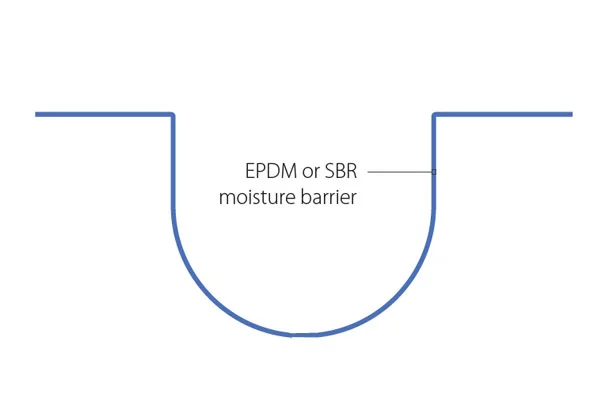
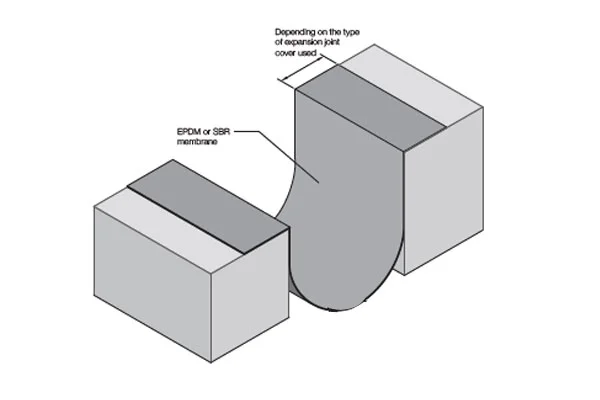
Finally, a moisture barrier layer is applied to the wall to impede the capillary action diffusion within the ancient bricks and the brick joints, as well as the combined effects of permeation flow through the wall’s weak zones and capillary diffusion [79]. A newer method for moisture protection of historical building walls is the injection moisture barrier method, which involves drilling holes along the brick corners and joints where a moisture barrier layer is needed, cleaning the holes, and then injecting a traditional polyethylene [80] to incorporate the moisture barrier layer within the wall, thus achieving a moisture-proofing and restoration effect (Fig. 10a). Knarud et al. [81] developed an intelligent moisture barrier (SVB) through a large-scale building envelope climate simulator to replace traditional polyethylene barriers. The SVB effectively improved the ability of the moisture barrier to suppress capillary action within the wall. However, the research conclusions also indicate that for actual construction conditions, the building as a whole is not a single wall, and the SVB did not exhibit significant effects in enhancing capillary action resistance at the wall’s ends and the connection points with other structural elements in the research. Further research could explore other measures to enhance the moisture protection capabilities at the ends and joints of the wall.
The disease situation that needs to be maintained and the principle of moisture proof repair of brick wall. a The principle of moisture-proof repair (b) Biological diseases (c) Large area concentrated precipitation of salt. (d) A large amount of salt is precipitated in a small area (e) Different positions of salt precipitation
Restoration techniques for mild damage of wall surfaces
For historical building wall surfaces that have missing damage due to salt efflorescence, hydration, or external forces, but with a radial damage range of less than 50 mm (Fig. 11b–e), as the depth of the damage is relatively small, there is no need for deep excavation of the damaged area. Traditional methods often involve adding brick powder or other solid waste materials to the base mortar material [14], which is obtained by crushing, ball milling, and sieving abandoned clay bricks from demolished or remnant old buildings. This mixture substitutes part of the ordinary cement in the mortar to produce a modern repair material with controllable performance. This material ensures that the repaired wall surface maintains good breathability and has a strong adhesion effect with the brick material. The process flow starts with high-pressure water cleaning of the surface of the ancient brick artifact to remove the weathered layer. Then, A rock reinforcement agent is applied to the surface of the repair area for preservation. Quick-embedding repairs are conducted on the damaged areas of the ancient brick with a depth greater than 2 mm and less than 50 mm using repair materials. Before the material completely cures, the filled areas are leveled and the brick joints are outlined. The repaired sections are then polished to conform to the original contour of the bricks (Fig. 11a). Finally, an odorless, transparent, permeable hydrophobic protective liquid is sprayed onto the ancient brick wall to provide post-repair protection.
Schematic diagram of the brick powder repair process. a Brick powder repair process (b) Minor damage to the edge of the brick (c) Bullet holes caused discrete minor damage to brick walls during the war (d) The whole surface of the brick is slightly damaged (e) Local slight damage of bricks
Against the backdrop of current research on solid waste utilization, the admixtures have evolved to include more options beyond just brick powder. Ayat et al. [11] have confirmed that using waste glass powder as a substitute for brick powder yields even better repair results, with the bricks repaired using glass powder mortar exhibiting an increase of 18.2% in flexural strength and compressive strength. The porosity of glass powder mortar is slightly lower but the overall difference is not significant, indicating good substitution potential. Lopez-Zaldivia et al. [10] modified traditional cement mortar by adding urban construction waste and incineration ash from waste incineration, confirming that the modified aluminate cement performs excellently, with clear indications that it is suitable for practical engineering applications in rapid structural repairs. Jin et al. [12] modified MPC repair mortar by incorporating fly ash, demonstrating that the modified MPC cement exhibits the characteristics of “rapid setting, high early strength, and high bond strength,” making it advantageous for rapid repair projects in historical buildings. They also provided material recommendation mix ratios for practical applications.
Utilizing brick powder or other solid waste ash to modify cement mortar for use in shallow-layer filling and repair methods for the surfaces of historical building brick walls aligns well with the principles of historical building restoration. It also satisfies the requirements for post-repair usage and timeliness, achieving a unification of the cultural and artistic value, long-term service performance, and aesthetic harmony of the historical building, while also promoting the research outcomes of solid waste utilization. However, compared to replacement repair methods, the process of using modified mortar for smoothing is relatively complex and the cost of materials is higher. It is necessary to consider the actual volume of the restoration project in conjunction with local conditions to develop a targeted repair plan that is compatible with the building’s characteristics and meets the restoration needs.
Restoration techniques for moderate damage of wall surfaces
When the ancient brick materials on the wall surface are severely weathered, leading to signs of material spalling, or when the average depth of damage on the wall surface is greater than 50 mm due to human carving and improper surface maintenance, it is considered moderate damage (Fig. 12a, b). In such cases, the damaged areas are repaired using a method involving painting and joint filling [15]. The first step involves cleaning the exterior of the repair area, removing surface microorganisms, overlying paint layers, and residual metal attachments from inappropriate repairs [13]. A chisel or similar tool is used to gently remove the wall paint layer to expose the ancient bricks, with a jet of water detergent used to rinse the brick surface and then rapidly dried to prevent moisture absorption by the brick pores. The cleaning process ensures that no damage is done to the original wall. Holes are drilled into the damaged area, filled with epoxy glue or mortar to a volume ratio of 1/3, and anchored with reinforcing steel bars [82]. After the anchoring bars are fixed, a steel mesh is attached along the contact edge between the anchoring bars and the ancient brick material. Cement lime or other waterproof mortar materials [83] are then used to repair the defects on the ancient brick surface. The choice of repair material should be such that it has reversible properties in the later processing stage and good permeability. Pinho et al. [84] have validated the applicability of materials such as ethyl silicate for reinforcing damaged parts of brick and stone artifacts. The study indicates that these materials effectively enhance the compressive strength, tensile strength, and relative dynamic modulus of the reinforced samples. They also demonstrate good compatibility with brick and stone materials and have a relatively durable reinforcing effect in environments with higher salinity and humidity; Normand et al. [85] compared the water absorption and hydrophobicity effects of ethyl silicate, nanoscale lime, and acrylic resin materials on brick and stone artifact samples after reinforcement. The curing effect of acrylic resin was very significant but had little effect on improving the hydrophobicity of the material. Ethyl silicate had a lower curing effect but demonstrated good hydrophobicity, and both materials exhibited good compatibility. Studies on lipid-based repair materials could refer to the research logic of the “multilayer electrode superposition method” mentioned above, combining the hydrophobicity and curing effects of the two materials to improve the repair effect from multiple perspectives, rather than focusing solely on maintaining or enhancing a specific property.
Ancient brick wall hook seam repair process. a Moderate damage in the middle of the wall (b) Moderate damage at the bottom of the wall. c Chemical planting bar and wall hanging net after basetreatment (d) Grouting grinding repair after hook joint construction and finishing treatment
After the repair of the ancient brick surface is completed, it is necessary to restore the overall original color of the building. Materials such as clay paste [86], brick sand [87, 88], and transparent glue mixtures [89, 90] are used to coat the wall surface, ensuring that the repaired area matches the color of the original wall. Midtgaard [86] has confirmed in his research that among various clay pastes, fibrous active white clay and PANGEL (R) S1500 material have good performance in terms of their adhesion to the repair subject. PANGEL (R) S9, due to its material’s porosity characteristics and water migration pattern, is shown to have a certain desalination effect while meeting the decorative needs. Sabine M et al. [89, 90] have studied transparent water-added mixtures for heritage building restoration and decoration, evaluating them from the perspectives of cultural relic protection and restoration principles. Their research indicates that plant-based glues and drying oils are more widely applicable, well compatible with wall surface decoration or as adhesives, and cause minimal interference to the attached materials. Such materials can also seal and protect the repaired wall surface from aging [91]. Finally, the brick joints are outlined, and a medium-thickness white lime mortar is prepared, following the process order of “from top to bottom, from left to right, first horizontal joints, then vertical joints” to ensure that the mortar joints are smooth and continuous, with the head joints full. After the mortar joints have dried, the repaired area is treated to match the overall color of the building, ensuring a harmonious and unified appearance (Fig. 12c, d).
This method has the advantages of convenience, low cost, and relatively low construction technical requirements. From the perspective of construction duration and cost, it has a certain cost-performance ratio. However, blindly choosing this method can interfere with the building wall to some extent, damaging its own historical and cultural value to a certain degree. It is suitable for situations where there is a large number of missing and peeling on the brick wall surface. To achieve a restoration that is both economical, timely, and sustainable, reference should be made to the above studies, selecting materials with good compatibility and obvious performance improvements. At the same time, attention should be paid to the control of the cost of the plan.
Restoration techniques for severe damage of wall surfaces
When the ancient brick materials on the historical wall surface are subject to severe weathering, resulting in substantial material spalling, or when the wall surface exhibits extensive material loss due to historical changes and human-induced damage, new bricks are selected and replaced using methods such as removal and subsequent re-infilling [13], as shown in Fig. 13. The specific treatment steps are as follows: First, the specific repair area should be marked, and the dimensions of the new bricks should be determined based on the specifications of the bricks in the wall to be repaired. An impact drill or hammer is then used to carefully remove the damaged bricks and mortar within the marked area to ensure that the new bricks can be inserted into their respective positions. Next, mortar is applied to the old brick positions and the new bricks are immediately attached to the wall. During the installation process, the position of the new bricks should be constantly observed to maintain the wall’s visual harmony. Finally, mortar is used to fill the gaps between the bricks and smooth the surface, allowing the mortar to cure and complete the replacement process. The selection of brick and mortar materials should be flexible based on the actual situation. New bricks should not only match the size of the old bricks but also have a color that is similar to minimize the visual impact of the repair. Additionally, the mineral composition, element types, and physical and mechanical properties of the new bricks should be similar to those of the old bricks. For sustainable restoration of historical buildings, there is a high requirement for the interface bond performance between the mortar and the substrate. The pore characteristics and hydration products of the mortar, to some extent, determine its bonding strength with the substrate. The internal water migration and redistribution significantly affect the durability of the repaired area. The impact of water exchange between different repair mortars and porous brick materials on the mortar’s pore structure and overall hygroscopic properties is a key focus in mortar performance research. Many scholars have conducted extensive research on this issue, including microscopic studies of mortar types [92], admixtures [93], and water-cement ratios [94]. Common approaches include using high-bonding strength and well-compatible mortars such as lime mortar [95], cement mortar [96, 97], and polymer mortar [98] as the base materials. These materials can be enhanced in terms of compressive strength, shear strength, and bonding strength through changes in their preparation methods [95], fiber modification [98], or component replacement [99]. In practical applications, the optimal material should be chosen from multiple perspectives, such as pore characteristics, mechanical properties, and durability, considering the environmental conditions and the specific characteristics of the building to improve the repair effect.
Material comparison and application of brick repair. (a) The case of discrete severe injury (b) The case of centralized severe damage. (c) Process the replacement area (d) Ancient building brick and archaizing brick
This method has been applied in restoration projects such as Yongqing Fang, adjacent to the site of the First National Congress of the Communist Party of China [29], and the Qingdao Changzhou Road Prison restoration [78]. During the construction process, on the basis of brick replacement, an transparent coating was sprayed on the ancient wall surface for protective treatment against corrosion and moisture. Additionally, in the Yongqing Fang project, a large amount of sand-containing cleaning agent was used to wash the new bricks to achieve an aged effect. The Qingdao Changzhou Road Prison, located in a region with high humidity, exhibited phenomena not observed in the Yongqing Fang project after the restoration. The brick blocks in the replacement parts of the prison showed obvious local peeling, weathering, and mold growth, and the situation was becoming increasingly severe (Fig. 14). Certainly, this is not a technical issue with the brick replacement method itself but rather a reflection of the traditional craft not being integrated with other protective and maintenance techniques suitable for the unique climatic environment of the historical building. If consolidators were used for pre-treatment before the repair and hydrophobic agents were applied to the wall after the repair for moisture protection, it might have enhanced the timeliness and durability of the repair. The method of brick replacement has high requirements for construction techniques and causes minimal disturbance to undamaged or slightly damaged ancient brick walls, to some extent reflecting the principle of preserving the authenticity of historical materials. The choice of replacement bricks is diverse and can be old bricks removed from the building interior or new bricks that have been artificially aged using technical means, such as regenerated waste geopolymer bricks [100], sustainable ecological bricks [101], and regenerated concrete bricks [102]. There are different choices for the restoration of walls with different protection levels and specific conditions, and this method still has strong applicability for historical buildings with a focus on historical style value. However, due to the differences in material characteristics between new bricks and mortar and the complexity of the building’s environment, brick replacement requires careful consideration of many practical factors to determine the type of bricks, mortar, pre-treatment before repair, and post-repair protection. It is also important to monitor the condition of the repaired area in a timely manner and take appropriate measures. Compared to other restoration techniques, brick replacement does not significantly shorten the repair cycle and has a greater impact on the original structure. If the “brick replacement” method is to be adopted for restoration, in the first step of determining the replacement range, it is advisable to avoid unnecessary positions from being chiseled.
Corrosion of Attached Building Brick Surface [78]
Restoration techniques for wall structural cracks
One of the characteristics of ancient brick materials in historical building walls is that they serve both as surface materials and structural elements. Many damages cannot be simply attributed to the deterioration of the ancient brick materials [103]. A significant portion of the damage is caused by a combination of structural factors and material deterioration. Therefore, the restoration of building walls includes not only the restoration of surface materials but also the repair of wall structural damage. Common structural damages in ancient brick masonry include vertical structural cracks, horizontal and oblique cracks, and large-area missing and loose materials [104].
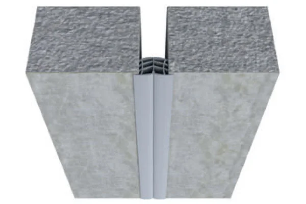
Before repairing vertical cracks in ancient brick walls, it is necessary to clarify the cause of the cracking. Cracks caused by vertical movement due to thermal expansion and contraction, wet expansion and dry contraction, or the lack of expansion joints can be prevented by adding expansion joints to reduce the constraints on the wall’s movement. Cracks indirectly caused by corroded metal components passing through beams and then through the wall, are first treated by removing rust from the surface and then reinforcing and treating the cracked ancient brick materials for corrosion resistance [16]; When ancient brick masonry is in an eccentrically compressed state, local stresses within the masonry can lead to significant vertical cracks (Fig. 15a, b). These cracks can be addressed by increasing the size of the upper structural components or expanding the size of the brick masonry foundation to transition from eccentric compression to axial compression. When a reinforced brick masonry is subjected to horizontal tension from tie beams, vertical cracks can be repaired by filling the cracks with shrinkage-compensating mortar and then reinforcing the area with constraint materials (Fig. 15c, d). Ebrahimzadeh [105] has demonstrated that reinforcing unreinforced masonry with polypropylene bands can increase the maximum strength and displacement of the masonry by 88% and 38% respectively, exhibiting excellent performance in resisting masonry cracking. Raouf [106] has studied the reinforcement of cracks in unreinforced masonry using metal, plastic, flat woven tapes, and strip-shaped vines. Evaluated in terms of the ductility coefficient and energy dissipation ratio of the repaired masonry, the flat woven tapes were found to provide the best reinforcement, with a ductility coefficient of 48.3 and an energy dissipation ratio of 12.7, effectively reinforcing the masonry while preventing secondary cracking.
Crack repair diagram of brick wall. a Filling a single crack in the wall (b) Filling multiple cracks in the wall (c) Grouting filling and steel hoop repair cracks (d) Repair of vertical cracks in brick masonry
Oblique cracks at the base of ancient brick masonry are typically associated with uneven settlement of the masonry, while those at the top are often caused by temperature or load effects. For stable oblique cracks, the repair methods for vertical cracks can be continued. Horizontal cracks can be caused by the contraction of structural frames or by bending of the masonry. The repair of horizontal cracks requires cutting continuous horizontal flexible joints at a certain interval on the masonry surface to release stress and prevent further cracking, followed by reinforcement of the cracked area. In recent years, there has been extensive research on the reinforcement of masonry structures using fiber-reinforced polymer (FRP) composites [107,108,109,110,111,112,113,114]. When using FRP materials for reinforcement and strengthening of masonry structures, it is essential to consider the differences in elastic modulus and strength between the structural material and FRP, which has a high elastic modulus and strength. The choice of reinforcement material should be based on a comprehensive assessment of the weathering degree and material properties of the structure surface [115]. FRP reinforcement can be used for masonry structures with no or light weathering. However, it is not recommended for masonry with extensive weathering. The constraint effect of FRP relies on a bonding layer to transfer the load to the structure. Therefore, during construction, attention should be paid to minimizing the number of interfaces and enhancing the bond strength. Applying “multiple small-width” FRP sheets evenly to the surface of the reinforced wall can improve the reinforcement effect of FRP materials.
Restoration techniques for rotted roof truss wood members
Wood member rot refers to the phenomenon of microorganisms such as fungi and bacteria eroding the material within the wooden components (Fig. 16c, f). When the ambient temperature exceeds 20 °C and the humidity is high enough to cause the internal moisture content of the wood to exceed 20%, microorganisms can thrive within the material, utilizing the organic matter in the wood as food and rapidly reproducing [17], leading to a decline in the mechanical properties of the wood until rot occurs. Additionally, when the ambient oxygen content is low, causing the wood to be anaerobic, or when the wood is exposed to long-term sunlight, leading to an increase in internal temperature, these conditions can indirectly accelerate the growth rate of microorganisms. The melting of winter snow on historical building surfaces in spring gradually increases the humidity as the temperature rises, and the water from the melted snow naturally drips down to the lower wooden components, leading to increased moisture content within the component pores, thus increasing the likelihood of rot. Upper wooden components such as beams, purlins, and rafters are also prone to rot due to their damp surface [19]. The choice of restoration methods should be based on the extent of rot in the wooden components. When the rotting section area is small and the depth of corrosion is less than one-third of the height of the wooden component, the treatment methods of peeling and patching [116] and veneering new wood [30] are employed (Fig. 16a). First, the rotting part of the component is completely removed using tools, and then filling materials or new wood are chosen based on the volume and morphological parameters of the missing part. Physical reinforcement methods are then used to secure the repair. Kloiber et al. [116] have studied various filling materials and found that earth-based mortar and modified traditional lime mortar exhibit extremely similar physical and mechanical properties in restoration practices. They have proposed a new material, casein/cheese-modified traditional mortar, which can prevent moisture in the air from entering the wood while achieving the repair function, thus preventing rot to some extent.
Schemdiagram of reinforcement and repair of beam and tietruss. a Tipping method (b) Bracket reinforcement method (c) Decay of wooden components outside the courtyard (d) Core material reinforcement method (e) End replacement method (f) Decay phenomenon of indoor wood components
When the area of the rotting section is large, and the depth of the vertical face is greater than one-third but less than three-fifths of the height of the wooden component, and the remaining intact section fails to meet the service requirements after bearing capacity calculation, the reinforcement is achieved through methods such as clamping wooden boards and supporting steel plates onto the damaged parts of the wooden component [117] (Fig. 16b, d). This involves treating the damaged area with preservatives, then repairing it with dry wood to match the original appearance and dimensions, and bonding it with water-resistant adhesives. Metal components may be added as necessary for reinforcement. The key to this repair method lies in the choice of fixing methods between new and old materials. Zhang et al. [18, 30] have studied the stress characteristics of different patch shapes at the repair interface and found that the shape of the patch has little effect on the component’s displacement under force, but both the rectangular and triangular patch shapes show stress concentration. In practical applications, whether using dowel and tenon reinforcement or metal component reinforcement, it is important to avoid “sharp corners” at the interface between new and old materials. When the depth of the rotting vertical face exceeds three-fifths of the component height, the root or the entire rotten part of the component needs to be replaced (Fig. 16e).
The methods described above can well maintain the integrity of the appearance of ancient wooden structural members, initially meeting the integrity requirements for the restoration of historical buildings. They are important restoration methods for wooden components. However, in most cases, these repair methods are irreversible to some extent, affecting the authenticity and reversibility of the materials. Additionally, the new materials embedded in the original components may not have the same properties as the old materials, and regardless of the method used to connect and fix them, the bond strength between the two materials will decrease over time, affecting the service performance of the wooden components later. For historical buildings with severe damage, the loss of authenticity caused by the repair process is inevitable. From the perspective of conservation principles, it is important to ensure that the repair has strong timeliness, selecting restoration materials with good compatibility and durability, and using fixing materials and methods that have the least impact on the building’s appearance, to retain the original value of the historical building to the maximum extent.
Restoration techniques for cracks in roof truss wood members
Compared to wood rot, the factors influencing wood cracking are more diverse. Wood members often have inherent defects such as wavy grain, pith, knots, and whorls. When these defects are located in structurally disadvantageous positions, they can lead to cracking of the members. Over time, under long-term load, the material strength of wood members gradually decreases, and their creep characteristics can affect the normal use of the members, reducing their durability and leading to cracking. The interaction between moisture and wood not only causes material rot but also drying shrinkage, which is one of the most representative behaviors of their interaction. Wood is an anisotropic biomaterial, which leads to different shrinkage rates in the tangential and radial directions of the wood. Typically, the radial shrinkage rate is less than the tangential shrinkage rate. When the moisture content of the material drops below the fiber saturation point [24], significant differences in shrinkage rates along different directions can occur, leading to cracking. Furthermore, the tangential tensile strength of different types of wood also affects cracking behavior; when the dry shrinkage stress caused by moisture loss exceeds the tangential tensile strength, cracking can occur [21, 22]. Therefore, the development of wood cracks is influenced by various factors such as environmental temperature and humidity changes, changes in moisture content, and the mechanical properties of the wood.
Beams, purlins, rafters, and other transverse members primarily serve to resist bending and shear, and their repair methods are based on the width of the cracks. When the crack width W ≤ 3 mm, it is considered a minor cracking phenomenon, and the cracked area is directly secured with an iron hoop for repair. When the crack width is 3 mm < W ≤ 30 mm, which represents a moderate cracking phenomenon, the crack can be filled with an insertion method and secured with an iron hoop on the outer layer [23]. When the crack width is 30 mm < W ≤ 1/3D and accompanied by rotting, the cracked area is first filled with epoxy-based polymers [20], and then secured with an iron hoop on the outer layer. When the crack width exceeds 1/3D and the limit, it is considered a severe cracking phenomenon, and the bearing capacity of the transverse wooden member must be checked. If it meets the stress requirements, the above insertion method can still be used for reinforcement; otherwise, additional reinforcement measures [118] (Fig. 17) must be taken. Reinforcement methods include mechanical reinforcement and support methods. The support method, on the foundation of filling and inserting the cracked area, supports the wooden member with vertical columns to prevent bending or even breaking due to the presence of cracks. Mechanical reinforcement methods involve adding reinforcing materials such as embedded steel (plate) or CFRP bars (plate) [119] to increase the strength of the wooden member, which is a repair method for shear cracks. If the cracking of the wooden member is severe and the above methods cannot meet the repair requirements, the damaged member must be replaced with new material. When large wooden columns, beams, and purlins sink or warp, smaller components such as dougongs, brackets, and longitudinal brackets as connection parts may also crack due to the unusual stress distribution. Since the connection components are complex in structure and numerous, disassembly and reinforcement are time-consuming and labor-intensive, with limited effectiveness. Therefore, it is preferable to use adhesives to reinforce the cracks in these components in their original state [120], striving to maintain the original appearance of the component as much as possible.
Schematic diagram of crack repair of beam and tiebeam. a Embedding method (b) Built-in core material method (c) Cracking of components outside the yard (d) Roof support method (e) Mechanical reinforcement method (f) Cracking of indoor fang bar (g, h)Outdoor rafter cracking (i) Indoor wood beam cracking
These reinforcement methods are widely used in the restoration of wooden components, aiming to preserve as much of the original undamaged parts of the components as possible, and they exhibit a certain degree of reversibility and sustainability. However, the use of these methods often involves a large number of metal components, which can easily disturb the appearance of historical buildings. In recent years, research on FRP materials seems to provide a solution to such issues. Campilho [121, 122] believes that the use of CFRP/GFRP combined with transparent epoxy resin for bonding wooden member cracks also produces good results. Todorovic et al. [123] found that GFRP BARS not only repair cracks in components but also increase the bending strength of wood members by 194%. Subic and other scholars [124,125,126] have shown that the introduction of FRP materials can increase the stiffness of the original components by 15%-29%, and even with a cross-section of FRP materials that is less than 1% of the cross-section of the component, the shear strength can increase by about 60%. The use of FRP materials effectively improves the impact on the appearance of the components and the rusting and discoloration of metal components. This combined new and old material repair scheme enhances the reversibility, sustainability, and historical authenticity of the restoration. In practical applications, the use of FRP materials to replace metal components in restoration should be actively promoted.
Restoration techniques for bending and sag of roof truss wood members
The bending phenomenon of wooden components such as beams, purlins, and rafters, which are subjected to long-term gravitational loads and experience material aging and performance degradation, is known as bending and sag. The repair methods are distinguished according to the degree of bending and sag [127, 128] . When the bending and sag are slight and have little impact on the bearing capacity of the wooden components, the damaged components can be turned upside down and used during the roof reconstruction and lifting. When the bending and sag are significant, i.e., the deflection exceeds the specified limit of the components, the repair is achieved using methods such as lower bracing and pull rod reinforcement, additional member reinforcement, or support methods. The support method includes two forms: pillar and additional support. When there are beams and purlins below the wooden beam, an additional support is set up on the beams and purlins using wooden columns; when there are no beams and purlins, the wooden beam is connected to nearby beams and frameworks using iron hooks. Lower bracing and pull rod reinforcement refers to setting up trapezoidal pull rods at the lower end of the wooden beam to form a truss structure to reduce its deflection. When the bending and sag are severe, leading to splitting or when calculations show that it cannot meet the force requirements, an I-beam or additional beam and purlin can be set up below the wooden component for support to achieve reinforcement effects (Fig. 18).
Schematic diagram of reinforcement and repair of beam and fangbeam. a Supporting-Roof Method (Pillar) (b) Bending of timber beams occurs. c Under-strut pull rod method (d) I-beam or attached beam Fangreinforcement. e Bending of the fang bar occurs (f) Supporting-roof method (Additional support)
Rafters, as important load-bearing components, are also prone to bending and sag, such as the easily bending and sagging structure of the golden character truss. To counteract the bending and sag, additional rafters can be added to the lower part of the damaged component or the addition of inclined supports using a supplementary support pedestal method. If small components experience bending and sag without severe material damage such as rot, they can be physically flattened during refurbishment and continue to be used. Dou-gong small components may also exhibit bending and sag due to uneven stresses and other factors. The repair method is distinguished by the relative deflection: when the relative deflection ≤ 1/120, a hardwood pad can be glued to the bending and sagging area for slight correction; when the relative deflection > 1/120, the bending and sagging component needs to be replaced [129, 130]. In the restoration of historical building roof trusses, the replacement of components is often used to maintain the overall shape of the wooden structure. However, frequent replacement of a large number of components can reduce the authenticity required by the restoration principles of historical buildings. Therefore, it is preferable to carry out infilling or attachment reinforcement from the perspective of raw materials as much as possible. Only when the damage causes severe insufficient material performance, and no repair method can meet the requirements, should replacement be considered.
Restoration techniques for drawer-out of roof truss wood member joints
In addition to the material of wooden components experiencing diseases and damage, various wooden member joints can also suffer from damage. The semi-rigid mortise and tenon joints are the main connection forms between wooden members in historical buildings. The “flexibility” of mortise and tenon joints reduces the overall stiffness of the structure and increases the ductility of the overall structure, which can reduce the inertial forces acting on the building during an earthquake and provide a certain level of seismic resistance. However, due to the large number and complex distribution of joints, they can also affect the stability of the structure [27, 28]. The radial shrinkage of wood itself can lead to the phenomenon of drawer-out of joints, and if the vertical load acting on the horizontal members is excessive or the structure encounters seismic forces, it can cause deformation of the members, which is also manifested as looseness and separation at the joint positions. This will reduce the effective cross-sectional area of the member, greatly decrease the bearing and force transmission functions of the joints, and subsequently affect the bearing capacity and safety of the structure.
Drawer-out phenomena primarily occur at the connections between horizontal and vertical members, between beams, purlins, and rafters, and at the internal nodes of the dougong structure. The restoration of drawer-out requires targeted design based on the degree of drawer-out. When the drawer-out occurs in a few locations and the drawer-out length is between 5 and 10 mm, which has little impact on the bearing capacity of the wooden framework, the drawer-out area will experience slight rotation, and the angle is within 0–0.014 radians, which will not affect the wooden framework. If the angle is ≥ 0.02 radians, the node will be subjected to compressive deformation entering the plastic deformation stage. At this time, the bearing capacity of the framework will decrease slightly with the increase in drawer-out. In such cases, the detached portion can be manually corrected and then reinforced using clamps [131], removable U-shaped steel [27, 132], iron hoops [132], or top connecting members [25] (Fig. 19a, c). When the drawer-out exceeds 100 mm or multiple nodes experience drawer-out, the bearing capacity of the framework will decrease significantly. Some nodes may have completely failed. In such cases, the decayed mortise heads should be removed first, and new mortise heads should be replaced [26]. The members at the node should then be re-fixed using bolts or adhesives (Fig. 19e, f).
Schemdiagram of reinforcement of wood member. a Rivet connection member (b) U-shaped steel connection members (c) Tin-wrapped connection member (d) Top iron ring connection member (e) Rivets secure the new tenon (f) Steel hoops secure new tenon
The rafters of the wooden frame are generally located at the beam heads. Under the pressure of the wooden purlins, the rafters can roll out of the shallow grooves along the beam heads. The repair method is distinguished by whether the end of the rafter is decayed or not: if the mortise end of the rafter is intact, it can be manually straightened and then secured with a wooden pad to prevent sinking, or replaced with bolts instead of the purlin head iron nails through the rafter joint, turning the purlin into a tension member for reinforcement. Alternatively, the rafters can be directly fixed using the same-shaped metal strips between them as iron plate purlins (Fig. 20). If the mortise end of the rafter is decayed, causing the rolling out, the decayed portion should be removed first, and the rafter can be connected with new mortise heads [133]. In addition, Alhawamdeh et al. [134] used different adhesives to re-fix the bonded surfaces of the rafters and purlins after initial fixation, and compared these samples with those fixed using spiral fasteners and iron nails (Fig. 21).The results showed that the combination of iron nails and polyether adhesive performed best, increasing the tensile strength of the nodes by 200% and 460%, respectively, and significantly enhancing the stiffness of the nodes. David et al. [135] found that the addition of polyurea coating increased the load-bearing capacity of the nodes by about 200–400%, while ordinary metal spiral fasteners only increased it by 25%. Additionally, the polyurea coating also prevents wood rot and cracking (Fig. 22). Such repair methods that combine chemical adhesives with internal metal components not only improve the performance of the repaired nodes but also minimize interference with the appearance of historical buildings, enhancing the sustainability of the repair and maximizing the authenticity required by the restoration principles of historical buildings.
schematic diagram of rod rafters and iron rafters. a The low side perspective of rafter tenon pulling phenomenon (b) Side perspective of rafter pulling tenon phenomenon (c) Iron rod rafter (d) Pull rod rafter
Schematic diagram of adhesive (a, b) and fastener plate (c, d) reinforcement [134]
Schematic diagram of polyurea coating reinforcement [135] (a) Black polyurea material with high elongation and low elastic modulus (b) White polyurea material with low elongation and high elastic modulus