
By Anthony M. Garcia, PE, BECxP, CxA+BE, CEI, Trinidad Martinez, RRO, CEI, and Ryan Foroughi

Cement plaster (stucco) has become increasingly popular as an economical and aesthetically appealing cladding on wood-framed and -sheathed construction around the country. This is accompanied by a reduction in water-diverting architectural features such as overhangs including proper flashing, and a poor understanding of installation requirements and building envelope principles, leading to low-quality installations and, for some, stucco failures that are rampant in the industry.
Historically, stucco was applied to stone, brick, or other compatible masonry walls, creating a monolithic section with high durability, vapor permeability, and drying potential. In this type of construction, the wall materials were highly absorptive; the lack of modern air sealing, insulation, and conditioning, and the high drying potential, meant these structures could get wet and dry with relatively little consequence. More recently (but not modern) stucco was often directly applied to wood lath. This system lacked an effective drainage layer and also relied heavily on the drying potential of the assembly. In addition, old growth wood was more durable than modern products when exposed to water.
Modern stucco today differs greatly from traditional methods. Instead of robust backing, wood-based backing often consists of oriented strand board (OSB) sheathing, which lacks durability when exposed to water. Instead of a compatible cementitious surface for adhesion, modern galvanized lath may corrode when repeatedly exposed to moisture. Modern water-resistive barriers (WRBs), improved air and thermal barriers, and increased reliance on mechanical heating and cooling mean drying potential in a wall assembly is greatly reduced when compared to historical wall assemblies, and condensation potential and humidity require careful management. While acrylic coatings or finish coats are sometimes used in stucco construction, the system itself is not typically referred to as “acrylic stucco,” and these finish layers are not directly addressed in the code sections under discussion.
As defined by the International Building Code (IBC), WRBs are not intended to manage or prevent infiltration from excess moisture that does not readily drain from the wall assembly. Instead, a WRB is intended to resist water while it drains or dries from the cladding. The 2015 IBC (and all subsequent editions) defines a WRB as “[a] material behind an exterior wall covering that is intended to resist liquid water that has penetrated behind the exterior covering from further intruding into the exterior wall assembly.” The authors note that a WRB is not waterproofing, meaning it is not intended to stop the ingress of bulk water under hydrostatic pressure. Instead, a WRB is intended to resist water while it drains or dries from the cladding.
In contrast, an air barrier is intended to resist the infiltration of air through the building enclosure, whereas a WRB is designed to resist the infiltration of bulk water. A WRB may include laps or joints that are not airtight. Although modern building assemblies often use products designed to function as both air and water-resistive barriers, this is not always the case. Since the code sections discussed here focus primarily on WRBs, further discussion of air barrier requirements is outside the scope of this section.
Section 1404.2 further defines a WRB as the following:
1404.2 Water-resistive barrier.
Not fewer than one layer of No.15 asphalt felt, complying with ASTM D226 for Type 1 felt or other approved materials, shall be attached to the studs or sheathing, with flashing as described in Section 1405.4, in such a manner as to provide a continuous water-resistive barrier behind the exterior wall veneer.
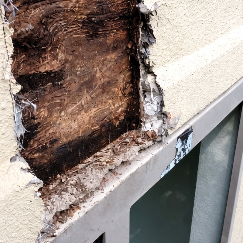
In addition, a lack of understanding and adherence to typical construction practices means the WRB can become littered with fastener penetrations due to improper lath installation as required in ASTM C1063, Standard Specification for Installation of Lathing and Furring to Receive Interior and Exterior Portland Cement-Based Plaster. For example, fasteners must be installed into framing members; commonly, these fasteners are blind fastened into wood sheathing, missing the framing member completely. This misunderstanding or ignorance of the installation requirements can lead to increased occurrences of cracks in the stucco cladding. All of these common construction defects further increase the amount of water that penetrates the wall assembly, with some of that water reaching the wood-based sheathing and framing and leading to numerous consequences, such as occupant nuisance, health and respiratory issues from biological growth (e.g. airborne mold spores), costly damages from rot or other water damage, and even structural failure.
Although codes have been slow to respond, the IBC has made regular changes to Section 2510, Lathing And Furring for Cement Plaster (Stucco), and subsection 2510.6, Water-resistive barriers, to reflect the increased risk associated with installing stucco cladding over wood-based sheathing when installation practices are inadequate. Wood sheathing serves important structural purposes in wood-framed construction, such as resisting lateral loads, and the type of sheathing itself is not inherently problematic when proper construction practices are followed. This article focuses on the progressive code changes regarding the WRBs and drainage requirements in this section from IBC 2015–2024 to help designers, contractors, and code officials understand how to comply with the code, improve the performance and durability of stucco-clad wall assemblies, and meet the project requirements for use of stucco cladding in a variety of project types, budgets, and locations.
The following is for use behind stucco, the WRB, the ability to drain water from the exterior wall assembly, and the water-resistance of other intervening layers, which have additional requirements. Changes to these requirements are captured for each code year under discussion in the following sections.
2015 IBC—not exactly the beginning
The 2015 IBC is the basis for the most common stucco assemblies and provides only basic requirements for the WRB behind stucco cladding and over wood sheathing. The authors also note that this assembly is less forgiving to defects in installation and have seen poorly installed assemblies on numerous occasions.
The 2015 IBC Section 2510.6 requires WRBs to be installed per Section 1403.2 where applied over wood-based sheathing, which references Section 1404.2 for minimum WRB requirements (see excerpt earlier in this article). Section 2510.6 also adds requirements for the WRB, including the requirement that the WRB “shall include a water-resistive vapor-permeable barrier with a performance of at least equivalent to two layers of water-resistive barrier complying with ASTM E2556, Type I.”
A Type I WRB is defined as a “water-resistive barrier with base-level water resistance” and tested in accordance to ASTM E2556, Standard Specification for Vapor Permeable Flexible Sheet Water-Resistive Barriers Intended for Mechanical Attachment. In addition, “each layer [must provide] a separate continuous plane and any flashing (installed in accordance with Section 1406.4) intended to drain to the water-resistive barrier is directed between the layers.”
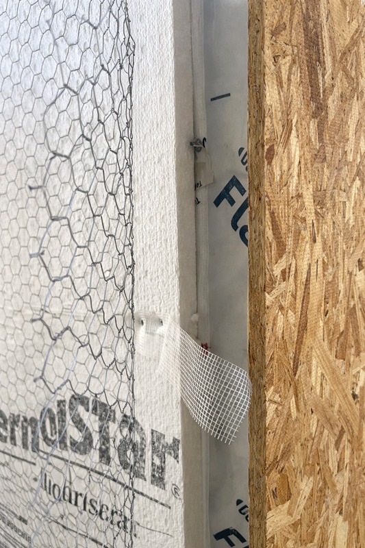
An exception to the requirement for two Type I WRBs is included in Section 2510.6, where the WRB can comply “with ASTM E2556, Type II and is separated from the stucco by an intervening, substantially nonwater-absorbing layer or drainage space.” A Type II WRB is defined as a “water-resistive barrier with enhanced water resistance” and tested in accordance to ASTM E2556, Standard Specification for Vapor Permeable Flexible Sheet Water-Resistive Barriers Intended for Mechanical Attachment. It is important to note that neither a “nonwater absorption layer” nor “drainage space” is defined, although the authors note that drainage spaces as little as 3.18 mm (0.125 in.) have been found effective, although 6.35 mm (0.25 in.) gap is typically recommended.1
For reference, a common exterior wall assembly complying with the 2015 IBC is presented as follows:
Layers (exterior to interior)
- Stucco
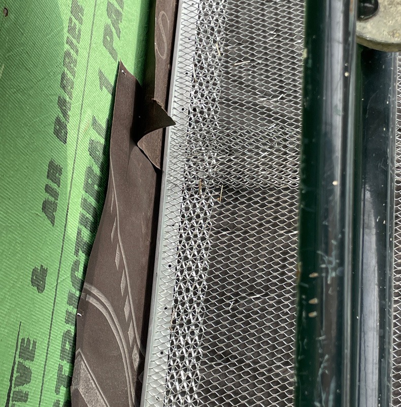
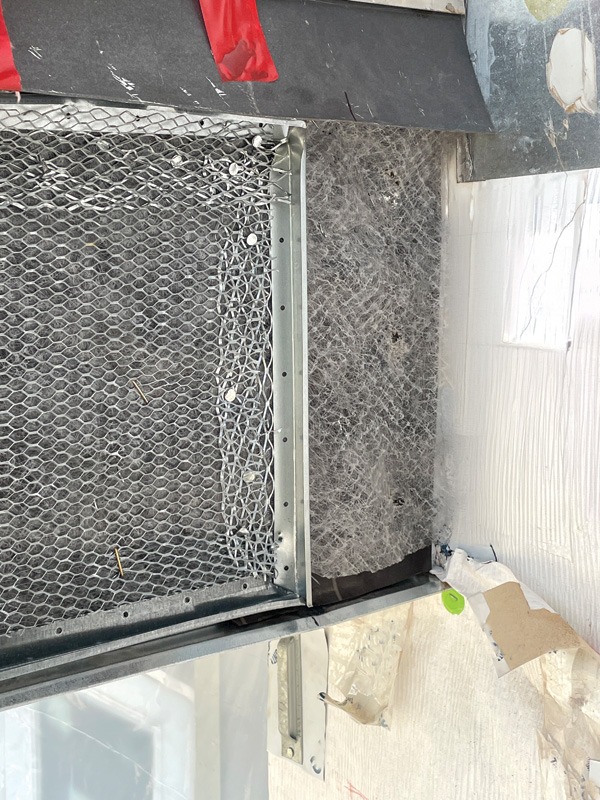
- Lath—Typically galvanized expanded metal lath as described in ASTM C1063, Standard Specification for Installation of Lathing and Furring to Receive Interior and Exterior Portland Cement-Based Plaster
- WRB—Common configurations:
- Two layers equivalent to a Type I WRB as defined in ASTM E2556, Standard Specification for Vapor Permeable Flexible Sheet Water-Resistive Barriers Intended for Mechanical Attachment:
- Grade D Building Paper (Type I WRB)
- Modern Type I WRB such as building wrap, etc.
- Two layers including one layer Type II WRB as defined in ASTM E2556, Standard Specification for Vapor Permeable Flexible Sheet Water-Resistive Barriers Intended for Mechanical Attachment:
- Grade D Building Paper (“intervening substantially nonwater-absorbing layer or drainage space”). Note that a drainage space used in this application is generally uncommon for this code cycle but may consist of furring strips, drainage medium, or similar assemblies attached directly through studs, with fasteners treated as recommended by the WRB manufacturer
- Modern Type II WRB such as fluid-applied air barrier
- Wood sheathing—Typically oriented strand board (OSB); less commonly, plywood
2018 IBC—Climate-specific changes
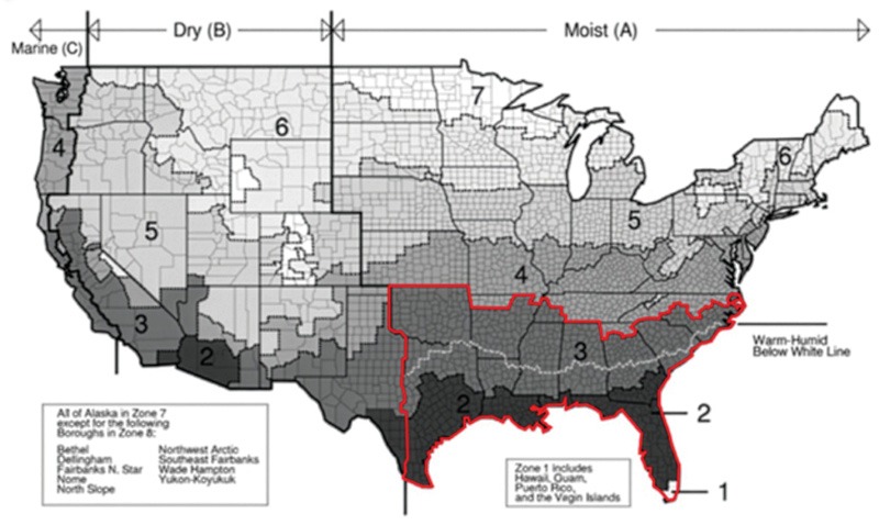
The 2018 IBC expands the requirements behind stucco by providing an exception in Section 2510.6.2 which requires “… a ventilated air space shall…between the stucco and water-resistive barrier…” in Climate Zones 1A, 2A, and 3A, which generally consist of moist southern climates, including much of the American South and Southeast as indicated within the figures on pages 20 and 21.
It is important to note that a ventilated air space is not defined in any of the subject publications of the IBC, which may cause confusion, misapplication, or ignoring of this specific requirement by designers, consultants, contractors, and building code officials. Studies show that a 9.53 mm (0.375 in.) air gap with openings at the top and bottom of the wall assembly provides venting of nearly 30 air changes per hour (ACH), which is the minimum gap the authors would recommend for best practices.2
For reference, a common exterior wall assembly complying with the 2018 IBC is presented as follows:
Layers (exterior to interior)
- Stucco
- Lath—Typically galvanized expanded metal lath as described in ASTM C1063, Standard Specification for Installation of Lathing and Furring to Receive Interior and Exterior Portland Cement-Based Plaster
- In Climate Zones 1A, 2A, and 3A, the code adds the following requirement:
- Ventilated air space
- WRB—Common configurations:
- Two layers equivalent to a Type I WRB as defined in ASTM E2556, Standard Specification for Vapor Permeable Flexible Sheet Water-Resistive Barriers Intended for Mechanical Attachment:
- Grade D Building Paper (Type I WRB)
- Modern Type I WRB such as building wrap, etc.
- Two layers including one layer Type II WRB as defined in ASTM E2556, Standard Specification for Vapor Permeable Flexible Sheet Water-Resistive Barriers Intended for Mechanical Attachment:
- Grade D Building Paper (“intervening substantially nonwater-absorbing layer or drainage space”). Note that a drainage space used in this application is generally uncommon for this code cycle but may consist of furring strips or similar spacers
- Modern Type II WRB such as fluid-applied air barrier
- Wood sheathing—Typically OSB; less commonly, plywood
2021 IBC—Raising the bar for climate-specific requirements
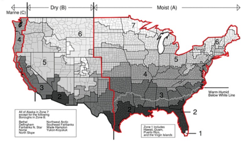
The 2021 IBC further expands the requirements behind stucco over the 2018 code by removing the consideration of thermal conditions and organizing requirements first by climate zone and then by WRB type. This shift replaces numeric thermal designations with moisture-based classifications (dry [B], moist [A], and marine [C]) to better address water management in stucco assemblies.”
For dry climates, the requirements are nearly unchanged from previous editions, except for the expansion of the acceptable materials between a Type II WRB and stucco cladding in Section 2510.6.1.2, now allowing for “a layer of foam plastic insulating sheathing or other nonwater-absorbing layer, or a drainage space” instead of just a generic “nonwater-absorbing layer or drainage space.” Once again, it is important to note that neither a “nonwater-absorbing layer” nor “drainage space” are defined.
For moist or marine climates, the ventilation requirement of the 2018 IBC is eliminated. Instead, “a space or drainage material not less than 3/16 inch (4.8 mm) in depth” is required in addition for the requirements of Section 2510.6.1.2 for Type I or II WRBs. Alternatively, a Type II WRB with “a minimum drainage efficiency of 90 percent as measured in accordance with ASTM E2273 or Annex A2 of ASTM E2925 [Standard Specification for Manufactured Polymeric Drainage and Ventilation Materials Used to Provide a Rainscreen Function]” is permissible under this version of the code.
The authors support any increase in drainage capacity of the exterior wall assembly, whether a true drainage space or from a “drainable WRBs.” A true drainage space is always preferred, as it requires understanding the drainage path in the exterior wall assembly and does not rely solely on the quality of WRB installation.
For reference, a common exterior wall assembly complying with the 2021 IBC is presented as follows:
Layers (exterior to interior)
- Stucco
- Lath—Typically galvanized expanded metal lath as described in ASTM C1063, Standard Specification for Installation of Lathing and Furring to Receive Interior and Exterior Portland Cement-Based Plaster.
- In climate zones A and C:
- For Type I or II WRBs—“a space or drainage material not less than 3/16 inch (4.8mm) in depth”
- For Type II WRBs—Drainable WRB
- WRB—common configurations:
- Two layers equivalent to a Type I WRB as defined in ASTM E2556, Standard Specification for Vapor Permeable Flexible Sheet Water-Resistive Barriers Intended for Mechanical Attachment, are typically
used so the second layer creates an additional plane for drainage: - Grade D building paper (Type I WRB)
- Modern Type I WRB such as building wrap, etc.
- Two layers including one layer Type II WRB as defined in ASTM E2556, Standard Specification for Vapor Permeable Flexible Sheet Water-Resistive Barriers Intended for Mechanical Attachment:
- Continuous insulation (“a layer of foam plastic insulating sheathing”), Grade D building paper (“other non-water absorbing layer”) or a drainage space
- Modern Type II WRB, such as fluid-applied air barrier systems, which function as more robust WRBs rather than serving to mitigate moisture originating from inside the building
- Wood sheathing—Typically OSB; less
commonly, plywood
2024 IBC—All types of backing
In addition to some clerical changes regarding the use of flashings for Type I and II WRBs, in sections 2510.6.1.1 and 2510.6.1.2, respectively, the 2024 IBC removes the stipulation for these requirements over wood-based sheathing, instead providing an exception to the requirements “where accumulation, condensation or freezing of moisture will not damage the materials.” The most common use of this exception would be cementitious backing, such as direct-applied stucco to concrete in a warm climate not subject to freeze-thaw action.
For reference, a common exterior wall assembly complying with the 2024 IBC is presented as follows:
Layers (exterior to interior)
- Stucco
- Lath—Typically galvanized expanded metal lath as described in ASTM C1063, Standard Specification for Installation of Lathing and Furring to Receive Interior and Exterior Portland Cement-Based Plaster
- In climate zones A and C:
- For Type I or II WRBs—“a space or drainage material not less than 3/16 inch (4.8 mm) in depth.”
- For Type II WRBs—Drainable WRB
- WRB—Common configurations:
- Two layers equivalent to a Type I WRB as defined in
ASTM E2556, Standard Specification for Vapor Permeable Flexible Sheet Water-Resistive Barriers Intended for Mechanical Attachment: - Grade D building paper (Type I WRB)
- Modern Type I WRB such as building wrap, etc.
- Two layers including one layer Type II WRB
as defined in ASTM E2556, Standard Specification for Vapor Permeable Flexible Sheet Water-Resistive Barriers Intended for Mechanical Attachment: - Grade D building paper (“intervening substantially nonwater-absorbing layer or drainage space”). Note that a drainage space used in this application is generally uncommon for this code cycle but may consist of furring strips or similar spacers
- Modern Type II WRB such as fluid-applied air barrier
- Wood sheathing—Typically OSB; less commonly, plywood
Conclusions
Building code updates are usually slow moving, with committees agonizing over the slightest revisions. Despite this, the requirements of section 2510.6 in the IBC is responding rapidly to the growth of the stucco industry and perceived risk, particularly when installed on wood structures. It is the author’s hope that this article will help educate designers and installers of the requirements of IBC section 2510.6 and provide a background on key decisions when designing a code-compliant stucco system. Key considerations include drainage requirements and WRBs robustness, which the authors recommend designing to the most stringent requirements of the 2024 IBC, including a minimum 4.8 mm (0.1875 in.) drainage space and a Type II WRB in all climates. This assembly is generally more forgiving to other installation defects, such as improper fastening or cracks in the stucco, which can stress even the most robust exterior wall system.
Notes
1 “With a gap of 3 mm (0.125 in.), capillary rise or suction is prevented. It is common to use a 3- to 6-mm (0.125- to 0.25-in.) gap as an effective capillary break. This gap prevents capillary suction between building components, uncoupling the cladding from the WRB/AB, and allowing free drainage.” Venting Cladding Assemblies Prevent Reverse Vapor Drive and Allow Vapor-Permeable Water-Resistive and Air Barrier (WRB/AB) Membranes to Enhance Wall Assembly Drying, Scott D. Wood, CBST; 33rd RCI International Convention and Trade Show.
2 Refer to “Review on ventilation rates in the ventilated air-spaces behind common wall assemblies with external cladding” by Mohammad Rahiminejad and Dolaana Khovalyg.
Authors

Anthony M. Garcia, PE, BECxP, CxA+BE, CEI, is a senior engineer at Terracon, specializing on failure investigation, remedial design, building enclosure consulting, and building enclosure commissioning. He has extensive experience in stucco construction and failures.

Trinidad Martinez, RRO, CEI, is a group manager at Terracon, leading multifamily building enclosure consulting through independent design reviews, field performance testing, and construction observation of building envelope systems.

Ryan Foroughi provides evaluation, assessment, and construction observation services for residential multi-family and commercial buildings. He also assists with Facilities Condition Assessment (FCA), Property Condition Assessments (PCAs), BE and MEP Construction Observations, BE and MEP Assessments, commissioning, and retro-commissioning services.
Key Takeaways
Modern stucco assemblies over wood-based sheathing face significant water management challenges due to changes in materials and installation practices compared to historical masonry-backed stucco. The evolution of the International Building Code (IBC) from 2015 to 2024 reflects growing recognition of these risks, with requirements progressing from simple dual-layer water-resistive barriers (WRBs) to mandates for drainage gaps and more robust, moisture-tolerant materials, particularly in humid climates. Proper installation, adequate drainage space, and use of enhanced Type II WRBs are now critical for mitigating moisture intrusion, reducing mold and structural risks, and improving durability. Designers should adopt the 2024 IBC’s most stringent standards for best results.